Building the VCF
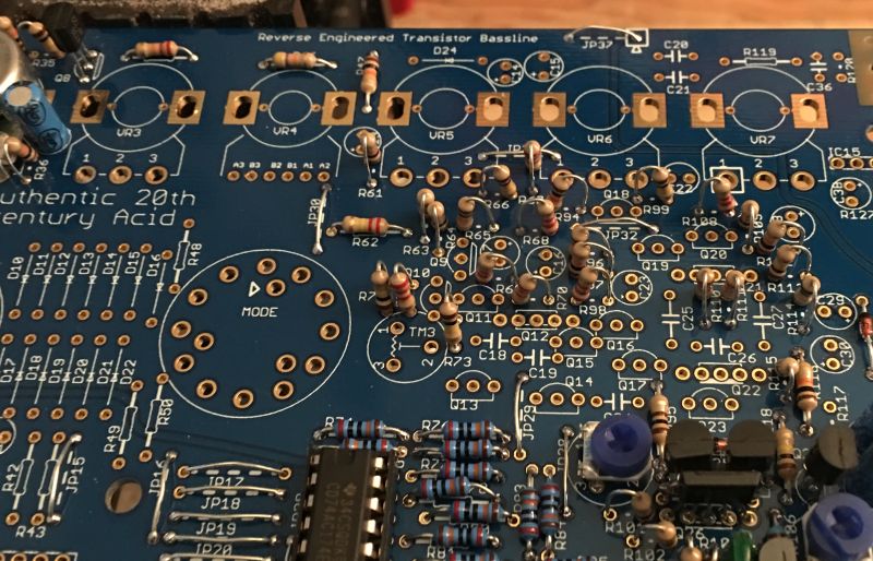
Fit all the resistors (R95 was fit in the preparation stage)
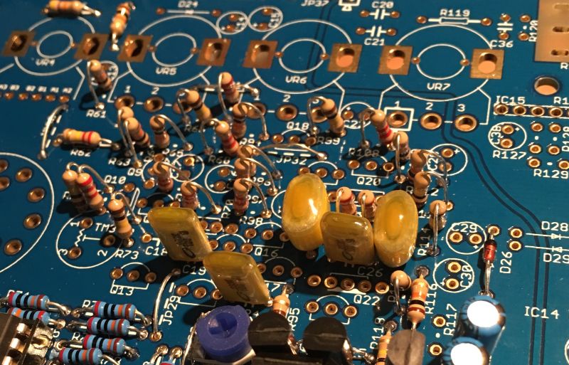
Fit the metal film capacitors.
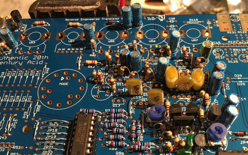
Fit the diodes and electrolytic capacitors.
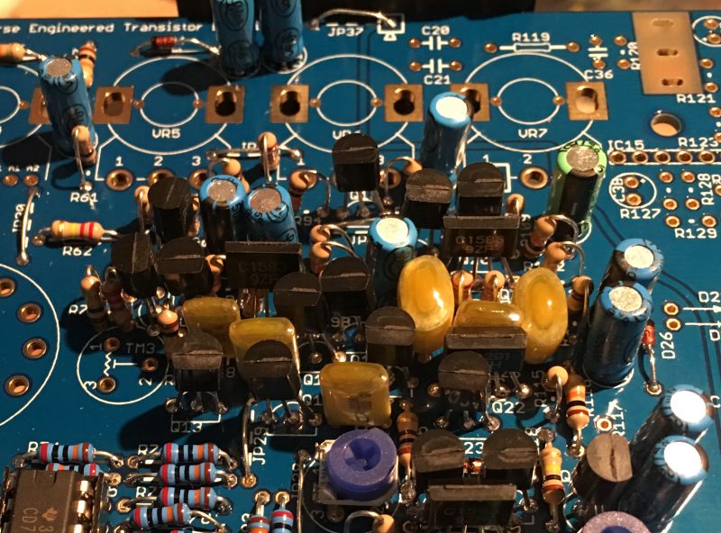
Fit the transistors.
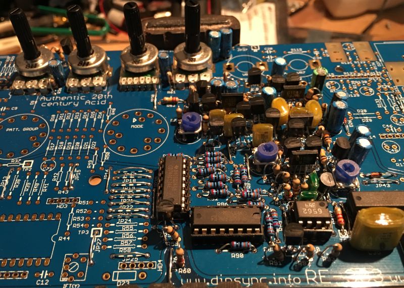
Fit the trimmers and potentiometers.
Take a moment to check your work, make sure nothing is missing and that there are no solder shorts or splashes. If you are satisfied then it’s time to test the VCF.
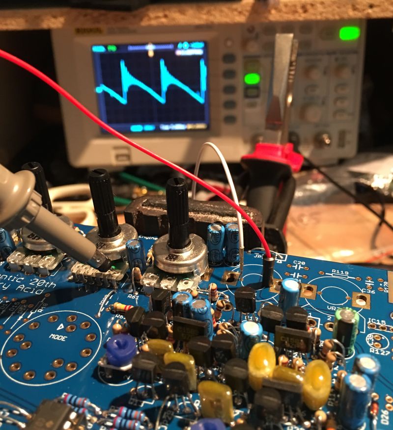
As before, connect the power supply and ground R90 (if your oscillator wasn’t running)
Set your scope to 100mv / 5ms AC and take some measurements from TP6 (the pins of VR4 resonance)
Turn the cutoff and resonance potentiometers and observe your oscilloscope. You should see the waveform changing from sinus looking to pronounced with resonance peaks with different knob positions.
If you see the changing waveform, you are all set and ready to proceed to the next section.
If you don’t see a waveform, check that you are testing correctly. Did you ground R90? Do you still have a waveform at the switch as before (this is before the VCF and should let you know if the problem is in the VCO or VCF)