Building the VCO
One small preparation stage for the VCO, we need to make the two 1K PTC tempco into a single 500R tempco that will fit in the available space.
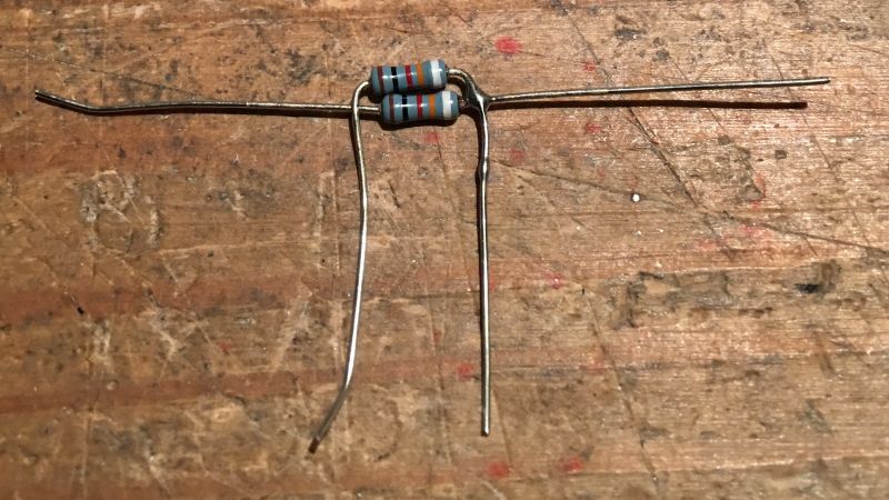
Form the parts as shown and solder each side.
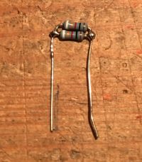
Trim the outer legs so that we end up with essentially a “tall” part ready for fitting.
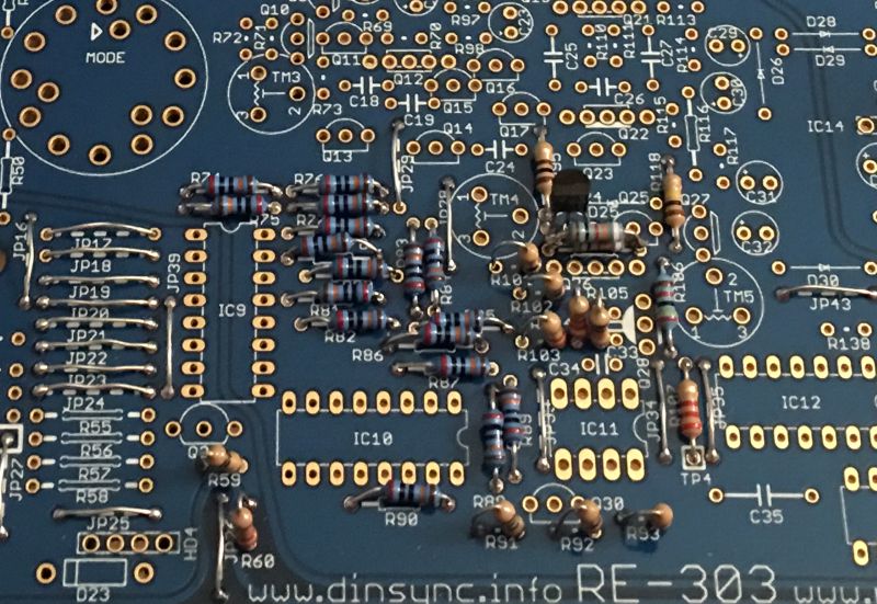
Fit the resistors and the tempco.
Fit the diodes and the poly capacitors.
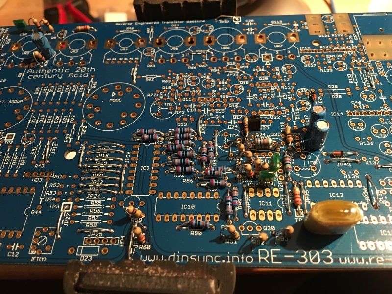
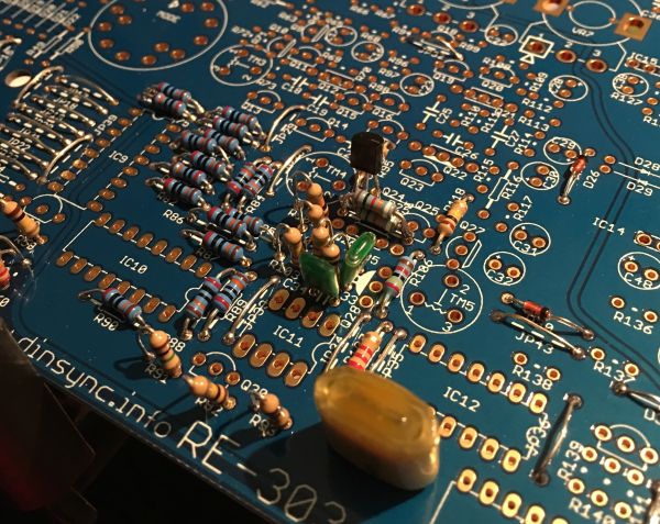
Fit the electrolytic capacitors.
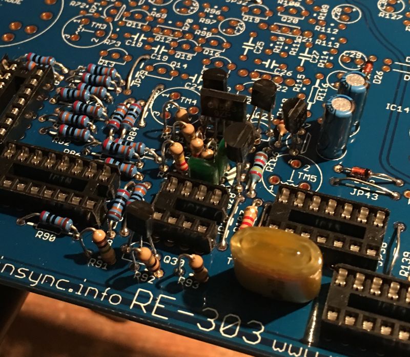
Fit the transistors. (and IC sockets if you are using them)
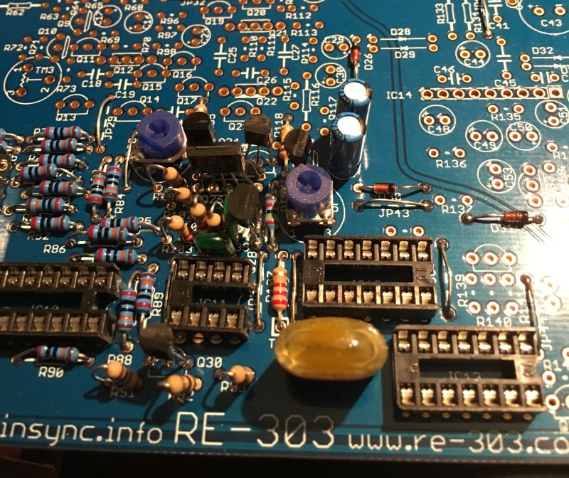
Place the trimmers and inspect your work so far, if you are satisfied everything looks ok then place the IC ́s, VR2 and the waveform switch.
Double check everything as it’s time to test the oscillator.
 |
|---|
| The picture shows me reading the square waveform from Q8 pin 2 |
Hook up the power as before. There are various places to measure the oscillator waveforms but perhaps the easiest is the center pole of the fitted waveform switch.
Set your scope to AC, 2v, 10ms and measure at the center pole of the switch, if you don’t see a waveform at this time you may need to ground the DAC to start the oscillator. You can do this by connecting the right side of R90 to ground.
If the oscillator fails to run, check your measurements are correct, check that you grounded R90. Check for solder shorts, or missing or misplaced parts. Check the power section is still ok.
Do not proceed until the oscillator is working as it will be more difficult to solve with a fully populated board.
If the oscillator runs, try turning VR2 and watch the frequency changes, switch the waveform switch and you should see either a saw or that special 303 square. If everything looks good, congratulations it’s time to build the filter.